(Sample)LR Low-pass Filter Design for PWM - Result -
Calculated peak-to-peak ripple voltage and settling time at a given PWM frequency and cut-off frequency or values of L and R.
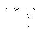
LR Filter
 PWM signal |
→ |
|
→Vout(s) |
| G(s)= |
628.318530718 s+628.318530718 |
Cut-off frequency
fc = 100[Hz]
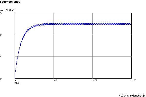
Final Vout value of the step response (without a ripple)
g(∞) = 2.5[V]
Peak-to-peak ripple voltage
ΔVpk-pk = 0.0785333573362[V](Duty=50%)
Settling time 0%→90% (0V→2.25V) (without a ripple)
tr = 0.0036646779944[sec]
| Transient analysis |