LR Low-pass Filter Design Tool

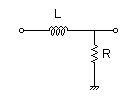
This page is a web application that design a LR low-pass filter. Use this utility to calculate the Transfer Function for filters at a given frequency or values of L and R. The response of the filter is displayed on graphs, showing Bode diagram, Nyquist diagram, Impulse response and Step response.

Calculate the transfer function for low-pass filter with L and R values

Vin(s)→ →Vout(s)
R=Ω L=H
p:pico, n:nano, u:micro, k:kilo, M:mega

Frequency analysis

Bode diagram
    Phase  Group delay
Nyquist diagram
Pole, zero
Phase margin
Oscillation analysis

Upper and lower frequency limits:
  f1= - f2=[Hz] (frequency limits are optional)

Transient analysis

Step response
Impulse response
Overshoot
Final value of the step response

Simulation time:
  0 - [sec] (optional)


Calculate the L and R values for the filter at a given frequency

Vin(s)→ →Vout(s)
fc=Hz
L=H (Omitted L=10, 1, 0.1, 0.01…)
p:pico, n:nano, u:micro, k:kilo, M:mega
Select Resistor Sequence:

Frequency analysis

Bode diagram
    Phase  Group delay
Nyquist diagram
Pole, zero
Phase margin
Oscillation analysis

Upper and lower frequency limits:
  f1= - f2=[Hz] (frequency limits are optional)

Transient analysis

Step response
Impulse response
Overshoot
Final value of the step response

Simulation time:
  0 - [sec] (optional)


LR Low-pass Filter Design for PWM

Sample calculation


PWM signal
→Vout(s)
fPWM=Hz
Duty Step   0%→[%]
PWM signal voltage
 VL = [V]  VH = [V]

L and R values of filter | Cut-off frequency

Cut-off frequency  fc = [Hz]
L and R values
    R=Ω L=H
p:pico, n:nano, u:micro, k:kilo, M:mega